
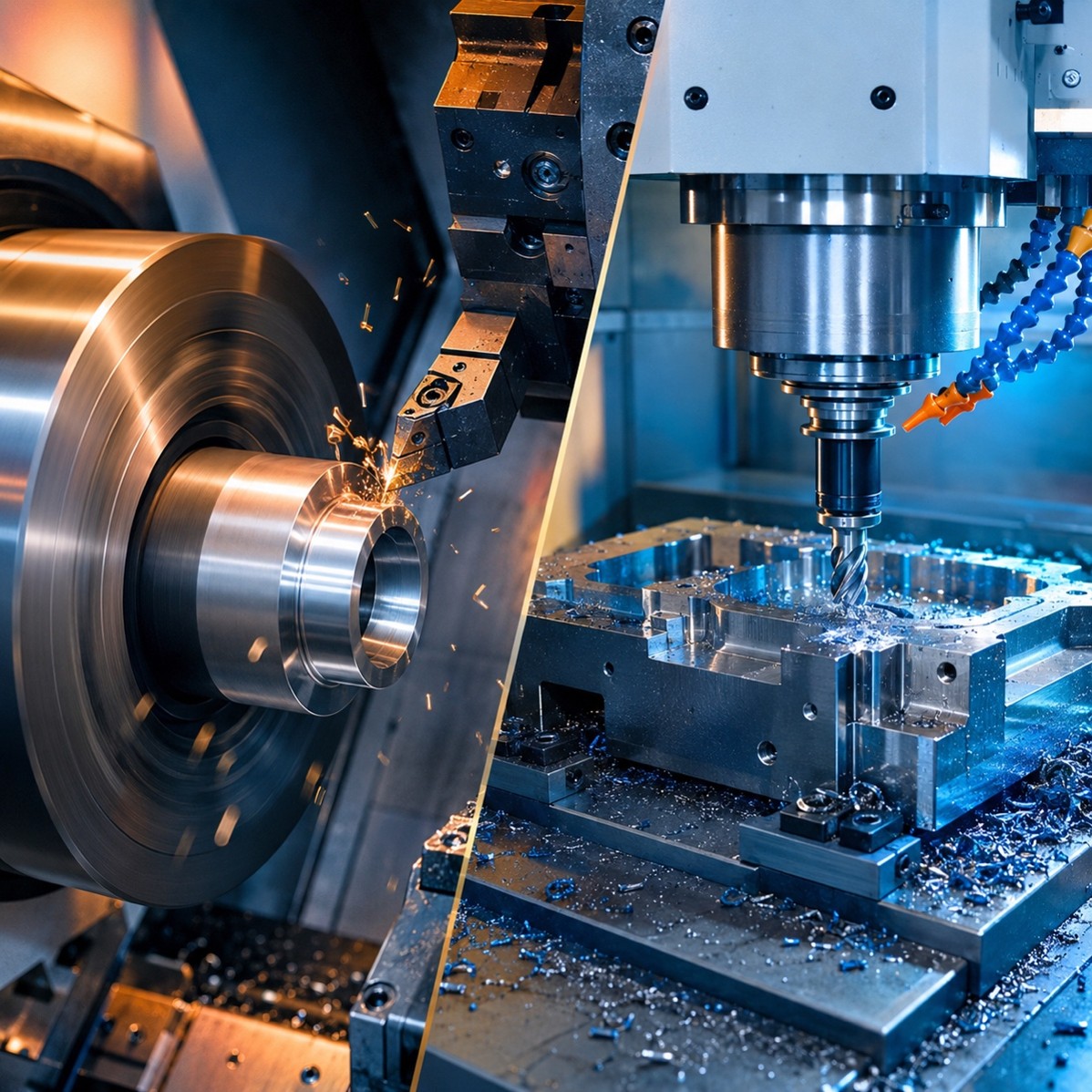
Turning removes material from a rotating workpiece using a non-rotating cutting tool, which makes it the natural choice for round, cylindrical geometry. Milling removes material using a rotating tool against a fixed or moving workpiece, which gives it the flexibility to cut flats, pockets, slots and off-axis features that turning alone cannot produce. Neither process is better in general terms. The part drawing decides which one wins, and a surprising number of components need both processes, often completed on a turn-mill centre rather than on two separate machines.
A shaft, a bracket and a valve body can all sit on the same purchase order, and each one belongs on a different type of machine before a single cutting parameter gets discussed. Getting this routing decision wrong does not always show up as a scrapped part. Sometimes it shows up as a part that technically passes inspection but takes twice as long to machine as it should, because it was forced through a process that was never suited to its geometry in the first place.
Two Different Ways of Removing Metal
Turning holds the workpiece in a rotating chuck while a non-rotating cutting tool moves along and across the spinning surface, shaving material away in a continuous, controlled path. The geometry this produces is inherently rotational: cylinders, cones, tapers and threads, because the tool is only ever cutting a circle at whatever radius it happens to sit at.
Milling flips that relationship. The cutting tool spins, often at several thousand RPM, while the workpiece stays fixed or moves beneath it on a table. Because the tool itself is the rotating element, it can approach the workpiece from multiple directions and cut features that have nothing to do with a circular cross section: flat faces, angled pockets, drilled and tapped holes positioned anywhere on the part.
This single difference in mechanism, tool rotating versus workpiece rotating, is the root cause of almost every practical distinction between the two processes that follows.
Where a Lathe Simply Outperforms a Mill
Rotationally symmetric parts play directly to turning’s strength, and the reasons go well beyond simply being able to produce a round shape.
- Cycle time on cylindrical stock. A lathe removes material along the full rotating circumference in a single pass, so a shaft or bushing clears stock far faster than a mill working the same diameter as a series of stepped circular passes.
- Surface finish on round features. The continuous cutting action on a lathe produces a smoother finish on cylindrical surfaces without the visible step-over marks that milling a curved surface tends to leave.
- Thread quality. Single-point threading keeps the thread aligned with other turned features in the same setup, making it a natural choice for many cylindrical parts.
- Bar stock efficiency. Turning from bar stock through a sub-spindle or bar feeder produces finished parts with minimal material waste compared with starting from a milled billet.
Shafts, bushings, pins, fittings and other parts defined primarily by outside diameter, bore and length belong on a lathe by default, and trying to mill this geometry from solid stock burns cycle time and tool life for no functional benefit.
Where Milling Takes Over
When flats, pockets or features away from the centreline become a major part of the design, conventional turning alone is no longer enough.
- Prismatic geometry. Brackets, plates and housings with flat faces, mounting holes and angled surfaces need a process that can approach the part from several directions, which a mill does and a lathe cannot.
- Pocketing and contouring. Cavities, slots and 3D contoured surfaces, common in mould tooling and aerospace structural parts, require the multi-axis tool movement that milling provides.
- Off-axis features. Holes and slots positioned away from the centreline of a part, common on valve bodies and manifold blocks, need a mill’s ability to reposition the cutting tool anywhere across the work envelope.
- Multiple reference faces. Parts needing several flat datum surfaces machined square to each other rely on a mill’s rigid table and multi-face access in a way a rotating chuck cannot replicate.
Comparing the Two Processes on the Factors That Actually Drive a Quote
| Factor | CNC Turning | CNC Milling |
| Ideal geometry | Cylindrical, rotationally symmetric | Prismatic, multi-face, off-axis features |
| Typical cycle time on suited geometry | Fast, continuous material removal | Slower, tool path dependent on feature count |
| Achievable tolerance on round features | Particularly well suited to tight tolerances on round features | Good, but generally wider than dedicated turning on purely round features |
| Surface finish on cylindrical surfaces | Excellent without secondary operations | Requires step-over control, can show tool marks |
| Material efficiency from bar stock | High, minimal waste | Lower when starting from solid billet |
| Feature flexibility | Limited to rotational geometry, plus live tooling for basic off-axis work | High, handles pockets, angled faces and complex 3D contours |
When a Part Genuinely Needs Both
Plenty of real components do not fit cleanly into either category. A shaft with a milled keyway, a turned housing with off-axis mounting holes, or a fitting needing both a precision bore and a flat wrench face all need turning and milling operations to reach a finished state. Running these on two separate machines means two setups, two fixturing operations and two chances to introduce alignment error between the turned and milled features.
Turn-mill centres combine a rotating spindle with live tooling and multi-axis milling capability, often allowing turned and milled features to be completed in one setup. Reducing refixturing can shorten cycle time and improve positional accuracy between related features.
Letting the Drawing Make the Decision
The right process for a component was decided the moment its geometry was finalised on the drawing, long before anyone opens a CAM package. A shop that defaults every job to whichever machine has capacity that week, rather than to the process the geometry actually calls for, ends up trading cycle time and tolerance for scheduling convenience. Reading the part correctly first is what keeps that trade from happening.
FAQs
Can a CNC lathe with live tooling replace a milling machine entirely?
Not for complex geometry. Live tooling on a lathe can handle off-axis drilling, slotting and some milling, but a dedicated machining centre is often better suited to extensive pockets, angled faces and complex 3D contours.
Is turning always cheaper than milling for round parts?
Generally yes, for parts that are primarily cylindrical, since turning removes material faster along a rotating surface and wastes less bar stock. Once a round part also needs several milled features, the cost comparison shifts depending on feature count and whether a turn-mill centre can combine both operations.
How do I know if my part needs a turn-mill centre rather than separate machines?
If the part has both rotationally symmetric features and off-axis milled details that must align precisely with each other, a turn-mill centre is usually the better call, since holding the part in one fixture reduces the risk of alignment error introduced by moving it between separate machines.
For enquiries, reach us as follows:
Email: sales@offshoresynergy.ae
Phone: +971 7 208 1300
Website: www.offshoresynergy.ae
